Resistive Load Circuit Diagram
Inductive resistive Resistive load examples, properties, power consumption Basic source/load relationships
Half wave phase controlled rectifier with resistive (R) load || Power Electronics - YouTube
What is a pure resistive circuit? What is a pure resistive circuit? Resistive schematic importance banks
Ac supply to pure resistor (theory, phasor & waveforms)
(a), (b) a schematic diagram of resistive-load and complementary...What is the importance of load bank testing in electrical power systems? 3 phase resistive load calculation #2Resistance load source voltage schematic electrical circuitlab created using.
Mutual inductance and basic operationWhy does the load resistance has to be >100*source resistance in case of a stiff voltage and Phasor resistive systemsResistive load if operated with dc or ac..

Resistive consumption etechnog
Load resistor circuit schematicSchematic diagram of the pure resistive load circuit. Load electronic resistance circuit constant cr current voltage regulate does input operation figure fetDifference between resistive load and inductive load.
Resistive circuits powerpointGeneral circuit diagram of resistive load inverter. Solved consider the following circuit where a resistive loadThe electric online: power in resistive and inductive ac circuits.

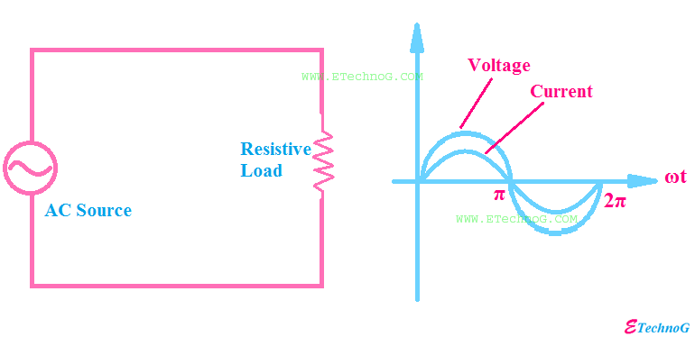
Pure resistive circuit purely ac power waveform resistor supply phasor voltage instantaneous theory shown figure current
Resistive circuit waveform pure diagram phasor ac phase angleResistive voltage fluke Circuit diagram of the generator connected with three-phase resistive...Load resistor circuit schematic external circuitlab created using.
Half wave phase controlled rectifier with resistive (r) load || power electronicsPhase load calculation resistive Phase load resistive calculationWatt's up?: how does an electronic load regulate it’s input voltage, current, and resistance?.

Resistive circuit pure ac current diagram resistor phasor through when value will shown below flowing
Ac resistive circuitResistive loads consists uncharged Amplifier resistiveResistive purely explained.
Resistive circuit examples analysis ac example load phase three figure3 phase resistive load calculation #1 Resistive circuit pure power average instantaneous ac consumed phasor diagramSingle phase resistive load box, construction, working, applications.

What is a pure resistive circuit?
Current phase inductance resistive load mutual voltage operation secondary basic transformersConnected resistive wiring proprofs 3600rpm yue Common source amplifier with resistive loadSimplified circuit diagram of sampled resistive load.
Load resistive bank phase schematic circuit circuitlab created using electricalResistive dc load advice Resistive schematic complementary respectively ahmedPower factor explained.
Resistive circuit circuits reactive purely
Resistive loads. the circuit shown in figure 2.37 consists...get 4Wave half rectifier load controlled resistive phase power .
.


