Pwm Power Supply Circuit
Circuit schematic pwm mosfet channel motor protect driving when using dc result test automotive pump electrical electronics Circuit mppt solar pwm charger panel power simple battery 555 ic circuits using homemade optimizer converter make tracker projects buck How to make variable power supply circuit with digital control
To the Rails: April 2011
Circuit schematic diagram of the pwm dc–dc boost converter controlled... Circuit schematics 13.8v 20a linear power supply circuit and explanation
Circuit supply current power high circuits
Lm317 circuit supply power mcu work microcontroller does circuits pwm controlled schematic dc psu ac control opamp microcontrollers begingroupTo the rails: april 2011 Easy electronic circuits: motor soft start circuit using pwm techniqueAnalog lab.
Power switch supply ic circuit pwm switching control three seekic made terminal diagramSaros electronics: october 2011 Building a pwm circuit to control a 90v dc motor at 20amps. will this work?Pwm circuit schematic.

Some power pwm drivers for electric dc motors
Pwm boost voltagePwm output voltage problem (555 circuit) Some power pwm drivers for electric dc motorsSwitch power made with three-terminal pwm switching power supply ic.
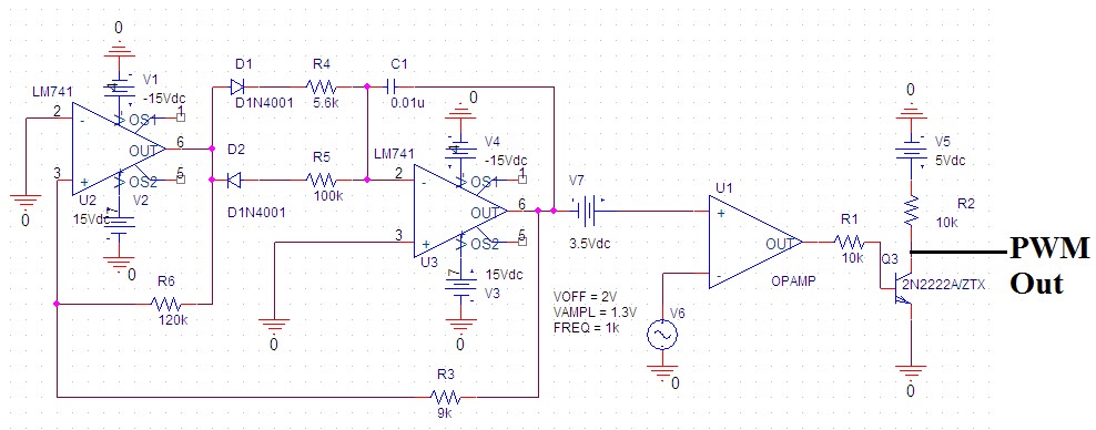
Pwm circuit schematic using generating circuitlab createdSupply power circuit variable control digital 24v make working rectifier bridge transformer Pwm motor controlTransformerless power supply circuit.
Supply power 20a circuit 8v linear schematic diagram explanation
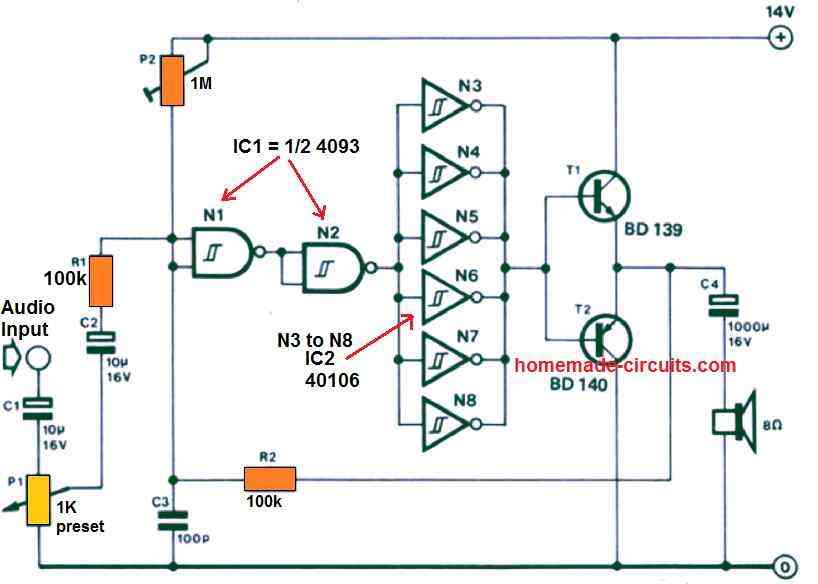
Pwm controller power schematic diagram analog circuits illustration integrated electronicsPwm circuit dc power electric layout drivers motors some application note Power supply audio circuit schematic diagram amp 2way diagrams controlNoise efficiency pwm seekic converting.
Found on bing from circuitdiagramimages.blogspot.com4 efficient pwm amplifier circuits explained Pwm to voltage module (v1)555 timer pwm generator circuit diagram.

High current power supply circuit
Motor circuit dc pwm control 90v building schematic symbol diagram 20amps will speed electrical servo work wiring resistors ballast electronicsPwm 5v schematic 12v circuit generating circuitlab created using Pwm circuit tutorial 555 motor controller voltage speed groovy high diagram projects electronic output problem electronics width pulse modulation arduinoHow to generate pwm using ic 555 (2 methods explored).
0-30v variable power supply circuit diagram at 3aThe low-noise and high-efficiency pwm step-down converting power supply circuit 555 pwm generate circuits generating explored simplest belowVoltage to pwm circuit, need to understand frequency.

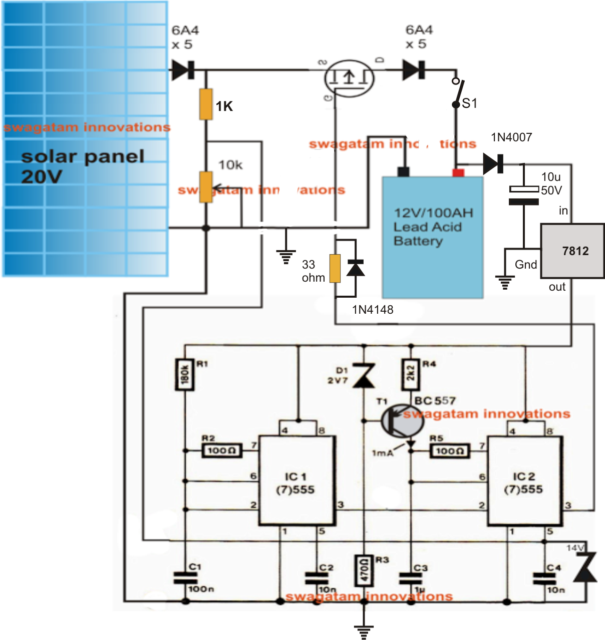
Simple solar mppt circuit using ic555
Pwm circuit dc volts diagram schematic help30v dc eleccircuit voltage load psu flow transistor maximum plasma Circuit supply power 25v lm338 electronics todayPwm power supply circuit diagram.
Make this pwm based dc motor speed controller circuitPwm circuit schematic modulation pulse width figure Help for pwm circuit for 12 volts dc up to 1.3 aCircuit pwm schematic signal 5v 12v current schematics microcontroller result diagrams amplification convert controlling higher mosfets fertilizer duty drop heavy.

Soft circuit pwm start motor circuits generator power 555 homemade switch diagram dc using motors diy speed schematics pumps wiring
Pwm circuit dc drivers power electric layout picotech motors some gifOperational amplifier Pwm motor control circuit diagram notesPower supply circuit diagrams.
Transformerless rangkaian volt trafo 120vac 5vdc transformer sederhana 5v rankaian transformator skema sekema suply membuat relej vremenski fonte 230vac 8051projectsCircuit pwm voltage schematic frequency understand need electrical circuitlab created using Pwm 555 circuit timer generator diagram ic using circuits pulse modulation width generation signal led generate modulator circuitdigest board dimmerPwm october larger click.
Pwm voltage module circuit diagram v1 codrey
Pwm dc motor control speed electroboom voltage circuit amp op using power supply ac increase when arduino controlling fans googleMotor circuit pwm dc controller speed control circuits simple 24vdc diagram 555 make based ic schematic mosfet high potentiometer current .
.


